
Case study
Functional V6 engine model
A working assembly in SolidWorks, not a static shape.
- Type
- Functional assembly model
- Software
- SolidWorks
- Services
- CAD design · 3D modelling
- Scope
- Design and motion validation
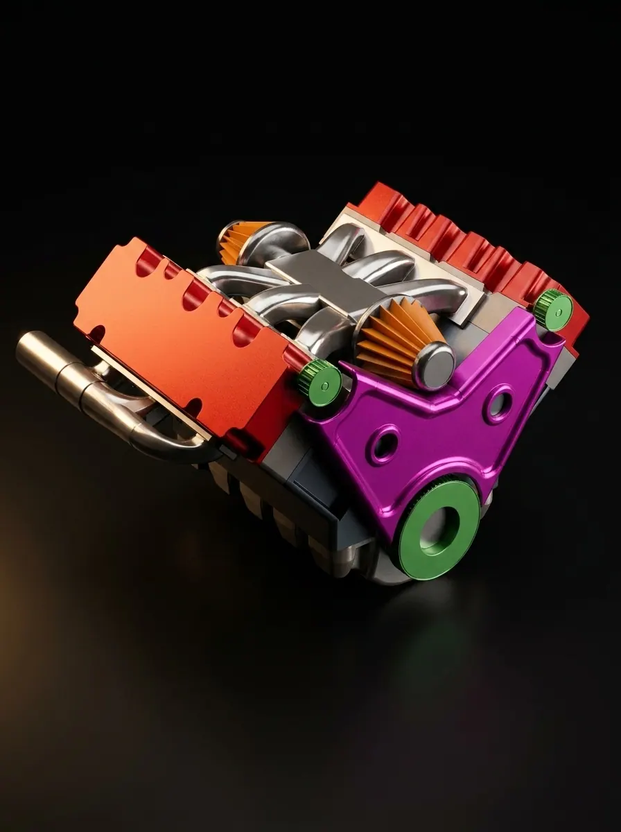
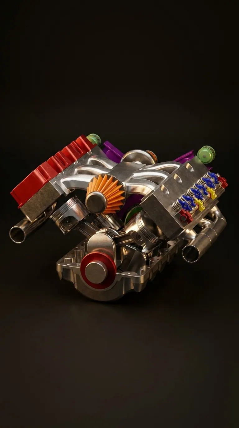
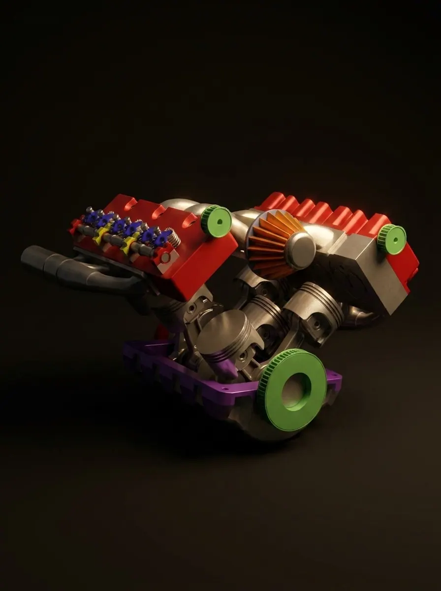
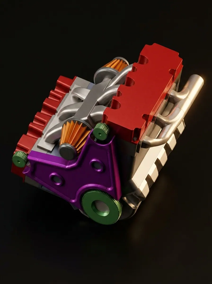
SolidWorks assembly of a functional V6 engine model with coloured components and timing gears
The problem
Anyone commissioning mechanical design has to judge whether a supplier can model a real mechanism or only a pretty solid. The difference does not show in a rendering: it shows in whether the parts actually relate to each other and move as they should.
The approach
A complete V6 engine was modelled in SolidWorks as a functional assembly — block, heads, exhaust runners, timing gears and rotating components — with the parts mated so the mechanism moves as it would in reality, and the assembly checked in motion rather than only inspected.
The outcome
A working demonstration of the CAD capability behind every other project here. When a part is reverse engineered, this is the standard of modelling underneath it.
Related work


Toyota Corolla KE72 rear brake light bracket
Reverse engineeringA discontinued bracket for a classic Corolla, rebuilt from the broken original.


Toyota Yaris 2023 tow hook cover
Reverse engineeringThe dealer's only answer was a whole new front bumper.


Industrial boiler door 3D scan — Yugadanavi Power Plant
3D scanningA corroded flanged door, scanned on site and rebuilt as a clean manufacturing model.
Yugadanavi Power Plant
Bring us the problem.
A part, a process, or just an idea. Tell us the situation and we will tell you the engineering route to solving it — honestly, even if that route isn't us.
MechaCAD Solutions, 368, Siyambalape North, Siyambalape 11607, Sri Lanka